


Article
From lab to field: designing rugged hardware that survives mass production
A hardware concept might work perfectly on a lab bench and still fail the moment it faces rain, freezing temperatures, vibration, dust, or long-term outdoor exposure. That gap between prototype success and real-world reliability is where many product programs run into trouble.

Why mass production breaks perfect design
There is also a second gap that gets far less attention and it is often the more expensive one. Almost anyone can design a good-looking, well-functioning product on a screen. The CAD model is perfect: every dimension nominal, every material ideal, every part identical. Mass production is none of those things. Manufacturing processes and the supply chain behind them introduce variation into every single unit, and a rugged product has to survive the field not at its nominal design values, but at the worst-case combination of that variation.
Whether you’re a startup looking to avoid expensive redesigns or an enterprise aiming to slash deployment risks, the objective is the same: don’t just build something that works once. Build something that keeps working, from unit number one to unit number one hundred thousand.
Why real-world conditions change everything
In the lab, conditions are controlled. In the field, they rarely are. A device may need to operate in driving rain, sub-zero temperatures, direct sunlight, coastal humidity, or environments where wind, dirt, shock, and repeated handling are part of everyday use. Those conditions affect everything from enclosure design and sealing to battery behavior, radio performance, material choices, and long-term reliability.
This is why rugged hardware can’t be treated as a standard product with a tougher outer shell added at the end. If the real operating environment isn’t considered early, the product may pass an internal demo but fail in deployment, creating delays, warranty issues, and higher lifecycle costs.
Engineering hardware for harsh environments: key challenges
1. Temperature extremes
Cold and heat both create hidden design challenges. Low temperatures can impact battery capacity, material flexibility, seal performance, and display behavior. High temperatures can accelerate component aging, increase internal stress, and affect charging, measurement accuracy, and overall electronics reliability. Temperature resilience must be designed in at multiple levels: component selection, power architecture, thermal behavior of the enclosure, battery chemistry and charging logic, and mechanical tolerances across the full temperature range
2. Water, humidity, and condensation
Water resistance is never just about a gasket. Real protection requires looking at the whole device architecture: enclosure interfaces, connectors, venting, assembly tolerances, materials, and the way the product behaves over time in changing weather. Humidity and condensation can be just as damaging as direct water exposure, especially when devices move between warm and cold environments.
Ingress protection ratings give this a common language. An IP rating defines how well a device resists solid particles and water: IP67 means dust-tight and protected against temporary immersion, IP68 extends that to continuous immersion. The most demanding class is IP69K: resistance to high-pressure, high-temperature wash-down, the kind a device faces in food processing plants, agricultural machinery, or vehicles that get pressure-washed daily. Importantly, IP68 does not automatically imply IP69K. The failure mechanisms are different. Static water pressure versus a hot, concentrated jet hammering directly at seal lines, so a product that survives a week underwater can still fail its first wash-down. The target rating has to be chosen based on the real deployment, and it shapes the sealing architecture from day one.
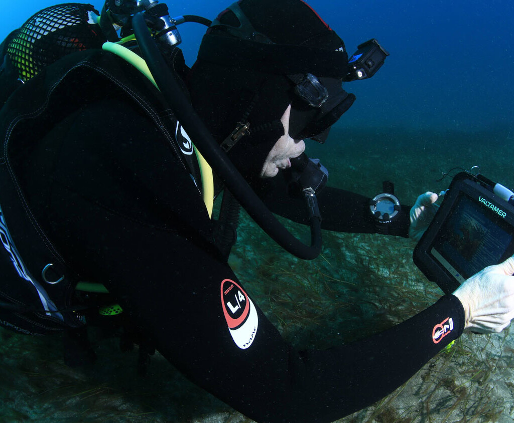
Valtamer’s underwater tablet, engineered with Haltian, during depth testing. Tested to depths of up to 150 meters.
Image © Valtamer
3. Wind, shock, vibration, and mechanical stress
A field device may be mounted on poles, walls, vehicles, machinery, or moving structures. That means it must tolerate more than static use. Wind load, vibration, impact, repeated servicing, and long-term material fatigue all affect mechanical performance. This is where industrial design, mechanical engineering, and test planning need to work together. If the mounting concept, enclosure structure, and internal layout aren’t designed as one system, reliability issues often appear only after deployment.
4. Power consumption and maintenance reality
In many real-world deployments, reliable power isn’t guaranteed and maintenance access is limited. Devices often need to operate on batteries for years or use low-power connectivity in remote locations. Power budgeting, firmware behavior, sensor duty cycles, and connectivity strategy must be treated as core product decisions rather than secondary optimizations.
The second gap: your CAD model will never be manufactured
Here is the uncomfortable truth about mechanical design: the part you drew does not exist. What exists is a population of parts, each slightly different from the next, produced by processes that drift, tools that wear, and materials that vary from batch to batch. A design that only works at nominal dimensions is a design that fails statistically: not on the lab bench, but somewhere in the field, months later, at a rate just high enough to destroy your warranty budget and your reputation.
Designing for mass production means designing for that variation. Three mechanisms deserve particular attention.
Injection molding: the stress you can’t see
Injection-molded plastics are the backbone of most rugged enclosures, and injection molding is a perfect example of how a manufacturing process embeds invisible risk into a part that looks flawless.
As molten plastic is forced into the mold and cools unevenly, internal stresses are locked into the part. The part comes off the tool dimensionally correct and visually perfect and it may stay that way for months. Then a cleaning chemical, a sunscreen residue, a hydraulic oil splash, or simply elevated temperature gives those frozen-in stresses a path to release. The result is environmental stress cracking: a crack that appears in the field long after every factory inspection has passed, often right where the enclosure was supposed to keep water out.
The risk is not uniform across the part. Gate locations, weld lines where two melt fronts meet, sharp internal corners, and areas around molded-in inserts are all stress concentrators. Whether they become failure points is decided by design choices, wall thickness transitions, gate placement, material selection, draft angles, made long before the first tool is cut. This is why material and geometry decisions in the concept phase are not styling decisions. They determine whether the enclosure is chemically compatible with the environments it will actually meet, and whether the molding process can produce it with low residual stress, shot after shot.
Tolerances: when every part is in spec and the product still leaks
Every dimension on a drawing carries a tolerance, and production will use all of it. Mold cavities differ slightly from each other in multi-cavity tools. Tools wear over hundreds of thousands of shots. Resin batches shrink differently. A second-source component is never quite identical to the first. Each variation is small and each part is within specification but tolerances stack.
Sealing is where this bites hardest. A gasket’s performance depends on its compression, and compression is the sum of a tolerance chain: housing depth, lid flatness, gasket cross-section, screw boss heights. If the design only delivers correct gasket compression at nominal dimensions, then somewhere in the production run there will be units where the stack-up lands at the wrong end and those units will pass the end-of-line test, ship, and leak after the first winter. The same logic applies to snap fits, press fits, button feel, connector retention, and antenna clearances.
Robust design means analyzing the tolerance chain deliberately: defining which dimensions are critical, ensuring the seal works across the full stack-up range, and, just as important, making the critical dimensions measurable in production so the line can catch drift before it becomes a field problem. This is design for manufacturing, assembly, and testability (DFM/DFA/DFT) in practice: not a checklist at the end, but a way of thinking that starts at the concept stage.
Supply chain variation: the factory is part of the design
Variation does not stop at your own drawings. Over a product’s life, components get replaced by alternatives, resin suppliers change, and production may move between lines or factories. Each change is individually reasonable and each one shifts the variation picture. A design that has margin only for the original supply chain is a design with an expiry date.
This is why supply chain decisions belong inside the product development process, not after it: component selection with volume availability in mind, supplier qualification, clear manufacturing specifications, and production test coverage. The handover to mass production should include not just CAD files, but the assembly instructions, test procedures, and quality criteria that keep the variation under control when the development team is no longer standing next to the line.
How to design for variation: experience, simulation, and real testing
So how do you actually verify that a design survives both the field and the factory? In practice it takes three complementary tools.
1. Experience from similar products
Most rugged-design failures are not new failures. Knowing where comparable products have leaked, cracked, or worn out and which materials, seal architectures, and mounting concepts have survived years in the field lets a team eliminate whole categories of risk before any analysis is run. There is no simulation model for judgment; it comes from having taken many products through to mass production.
2. Simulation
Simulation is the cheapest place to fail. Long before any tooling is ordered, structural and flow analysis can show where a waterproof enclosure is most likely to leak, what drop orientation and height will crack the housing, how wind load stresses a mounting interface, and how a molded part will warp and where its stresses will concentrate. Finding these answers in a model costs a fraction of finding them in a tooling revision – and a tiny fraction of finding them in a field recall. Simulation also makes tolerance questions concrete: you can test the seal at the worst-case end of the stack-up without ever building a worst-case unit.
3. Environmental and reliability testing on real prototypes
Simulation narrows the risks; physical testing proves the design. Environmental and reliability (ENVI/REL) testing puts actual prototypes through temperature cycling, humidity, water ingress, drop, vibration, and accelerated aging the compressed equivalent of years in the field. The sequencing matters: early engineering prototypes (EVT) validate that the design works at all, while design validation (DVT) prototypes are built using the final materials and final manufacturing processes. That distinction is critical for everything discussed above. A 3D-printed prototype tells you nothing about the internal stresses of an injection-molded part or the real behavior of a production tolerance chain. Only parts from production tooling carry production variation which is exactly what DVT is there to expose. Finally, production validation (PVT) verifies the manufacturing line itself: that the process produces conforming units repeatably, at yield, with the test coverage to prove it.
That progression, concept, detail engineering, EVT, DVT, PVT, is not bureaucracy. Each stage is designed to surface a specific class of variation before it reaches the customer.
A prototype isn’t enough
This is why assuming a working prototype is close to a finished product is one of the most common, and costly, mistakes in hardware development. A prototype proves that something can work once, built by experts, from hand-picked parts. A production-ready product proves that it can be built repeatedly, by a factory, from real supply-chain parts, tested efficiently, certified, and still perform after years in the target environment.
In practice, that means asking tougher questions early:
- Can this design be manufactured consistently across cavities, batches, and tool life?
- Does the seal architecture work across the full tolerance stack-up, not just at nominal?
- Are the chosen materials compatible with the chemicals and temperatures of the real deployment?
- Can critical dimensions and functions be tested in production, at line speed?
- Will component choices still be available and equivalent in volume production?
- Will it meet the certification and ingress protection requirements of the actual use case?
What startups and enterprises both need
Startups and large corporations often begin from very different positions, but the hardware challenges are surprisingly similar. Startups need speed, focused investment, and technical choices that won’t limit future scaling, and they can least afford a tooling revision or a field-failure wave. Enterprises need confidence, process discipline, and a development model that reduces manufacturing, quality, and compliance risk across a more complex organization.
For both, success depends on the same fundamentals: clear product requirements, realistic environmental assumptions, deliberate tolerance and material engineering, rigorous verification on production-representative hardware, and a controlled path from prototype to repeatable production. The difference is not whether these things matter. The difference is how early they are addressed and the earlier, the cheaper.
Turning vision into field-ready reality
Designing rugged hardware is risk management, and the biggest risks are the ones that don’t show up on a screen: frozen-in molding stresses, tolerance stack-ups, supply chain drift. Managing them takes hardware, mechanics, RF, embedded software, and manufacturing expertise working as one team from the concept phase onward supported by simulation, environmental testing, and a verification process built around production-representative prototypes.
At Haltian, we’ve taken products from idea to mass production for over a decade, including devices built for the toughest environments, such as Valtamer’s touchscreen tablet, engineered to operate reliably at depths of up to 150 meters underwater, and C-THRU, the wearable thermal imaging device we built with Qwake Technologies to help firefighters see and navigate through smoke. We don’t just design devices that work on the bench, we engineer products that survive the field and the factory.
If your next product needs to do both, let’s talk.